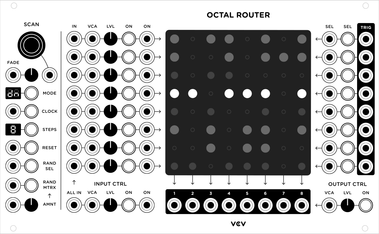
Route a signal into 8 different outputs. Switch between other input signals, and choose which outputs they are routed.
Interpolate between rows smoothly or immediately, forward or backward, randomly or exactly.
Includes two smaller sequential switches with CV-controllable scan and step number.
Octal Router Manual

Scanning
The SCAN knob and its CV input increase/decrease the selected row of the routing matrix. A signal ranging from 0V to 10V scans across all enabled rows in the matrix. For example, if all 8 steps are enabled, each increment of 10V / 8 = 1.2V increments the selected step by one, until the first step is reached again at 10V.
The FADE knob and its CV input allow smooth crossfading between rows with the SCAN input and knob. At its lowest setting (hard left and 0V), rows advance instantaneously. At its highest setting (hard right or 10V), the rows crossfade linearly between the current row and the next, determined by the current sequence mode.
Sequencing Controls
The MODE switch cycles through four different sequence modes.
- Forward advances the selection downward
- Reverse advances the selection upward
- Pendulum alternates between forward and backward
- Random advances to a different randomly-chosen row
Right-clicking on the LED mode display opens a menu for faster selection of modes.
The CLOCK button and trigger input change the selected row. A trigger is detected when the signal reaches 2V after dropping to or below 0.1V.
The STEPS button limits the maximum number of matrix rows to be used in the sequence. Like the MODE display, you can right-click on the STEPS display to quickly set the number of steps.
The RESET button and trigger input reset the selected step to the first row.
Random Controls
When the RAND SEL button or input is triggered, the switch jumps to a random step. This has the same effect as receiving a CLOCK trigger in Random sequence mode, but it can be used regardless of the current mode.
The RAND MTRX button and trigger input randomize the state of the routing matrix. The AMNT knob and CV input set the amount of randomization to apply when a RAND MTRX event occurs. At 0% no randomization occurs, and at 100% every matrix node has a 50/50 chance of being muted/unmuted.
Inputs
The INPUT CTRL section contains 8 inputs which are routed to the rows of the matrix. The VCA of each row has full gain at 10V and is bypassed when unpatched (i.e. no attenuation is applied). The LVL knob applies additional attenuation to the input row. Click the ON button to mute/unmute the input row entirely, or patch a trigger in the ON input to toggle the ON state of each row. If no cable is patched into a row, the ALL IN signal is used instead, with its own VCA, level knob, and mute switch.
Routing Matrix
The large 8x8 matrix display displays the routes from each input row to each output column, like a pin matrix. Click a node to mute/unmute the route, or click and drag to quickly mute/unmute a group of nodes. Right-click the matrix to invert, fill, or clear all nodes.
Outputs
Each column output below the matrix uses the signal from the currently selected row if it is unmuted, which is represented by a bright LED glow from the routing matrix. The OUTPUT CTRL section contains a VCA, level control, and ON switch, which affect all 8 column outputs.
Row Selection
To manually select a row, send a trigger to the SEL input, or click the SEL button. When a new row is selected by any means in the matrix, a 1ms pulse is generated on the row’s TRIG output. You can use these features, for example, to jump from one row to another by plugging a cable from a TRIG output to a SEL input.
Router 1:4 and 4:1 Manual
The VCV Router plugin includes two similar sequential switches based on Fundamental Sequential Switch 1 & 2.
Sequencing Controls
The STEPS display shows the number of enabled steps for the sequential switch. Click or send a trigger into the - or + inputs to decrease/increase the STEPS value, or control it directly using its CV input.
The CLOCK trigger input and button advance the sequential switch, and the RESET trigger input and button set the current step to 1.
Right-click on the panel to set the sequence mode in a context menu. Each mode is described in the Octal Router section.
Scanning
The SCAN input sets the step directly from a voltage. A 0V signal sets the step to 1, and 10V signal sets the step to its maximum, depending on the number of enabled steps. If a cable is plugged into this input, CLOCK and RESET events are ignored.
Inputs / Outputs
Router 1:4 routes 1 input to 4 outputs, while Router 4:1 routes 4 inputs to 1 output. When a trigger is detected in a SEL input, the switch jumps to that step. The TRIG trigger outputs generate 1ms triggers when the switch is changed to that step.
Router Changelog
1.0.1 (2020-04-01)
- Fix bug where Octal Router cells could be accidentally toggled by dragging your mouse over them.
1.0.0 (2019-06-18)
- Port to v1
0.6.1 (2018-08-10)
- Save direction mode of Router 1:4 and Router 4:1 to patch file.
0.6.0 (2018-02-28)
- Initial release