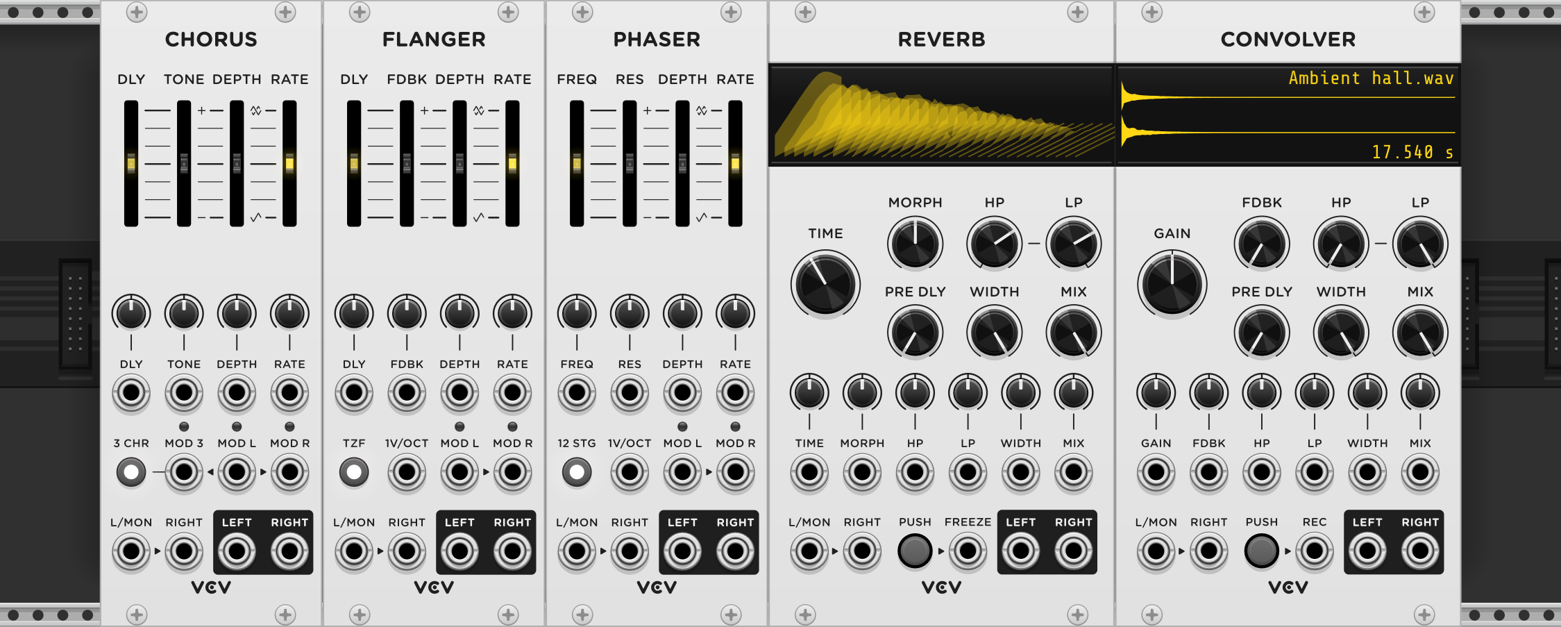

VCV Chorus
A chorus effect duplicates an individual sound into an ensemble of multiple sounds, each delayed by an LFO-modulated amount of time. The changing delay time of each signal shifts its pitch, so the combined signal resembles an orchestra of multiple slightly out-of-tune instruments, creating a richer sound.
Signal path
VCV Chorus contains one delay path for each L/MON and RIGHT input and can operate in mono, stereo, or mono-to-stereo modes. Each delayed (wet) signal is mixed with the original (dry) signal and sent to the LEFT and RIGHT outputs.
Right-click the panel and select “Invert left wet signal” to invert the left channel’s delay line before it is combined with the dry signal. This behavior is present in certain hardware chorus effects and can be used to enhance the stereo image.

The DLY fader controls the base amount of delay time for each wet signal, before bipolar modulation from the LFO is applied.
TONE applies EQ to the wet signal, with a brighter sound for positive values and a darker sound for negative values.
The delay time is modulated by an internal sine LFO. The DEPTH fader controls the amount of this modulation, and the RATE fader controls the frequency of the LFO. Negative depth values apply the same modulation amount to both channels. Positive values apply opposite modulation amounts to each channel, with 0° and 180° phase, creating a rotating stereo effect.

External modulator
An external CV signal can be added to the internal modulation for the left and right channels using the MOD L and MOD R inputs. This allows a complex waveform, sequence, or any arbitrary CV signal to control the delay amounts. If MOD R is unpatched, the MOD L signal is used for both channels.
3rd delay line
Enable the 3 CHR button to add a third chorus line to the mix of both left/right channels. The delay time is modulated by a separate LFO with 120° phase. This effect is known in hardware as a “tri-chorus” or “ensemble effect”.
The MOD 3 input adds external CV control of the delay, and if unpatched, the MOD L signal is used.


Starter tip
Set TONE to a positive value to filter the low frequencies of the wet signal. This is commonly used to thicken basslines without creating muddy lows.
A negative TONE value filters the high frequencies, as was done by vintage analog chorus hardware to avoid high-frequency noise from early delay circuits.
Expert tip
The stereo width of VCV Chorus can be enhanced or reduced with VCV Mid/Side by processing the left/right channels and adjusting the WIDTH parameter.
Enable VCV Chorus’ 3rd delay line, use a dark (negative) TONE value, and mix its left/right outputs to mono to create an effect similar to vintage string ensemble chorus hardware.

VCV Flanger
A flanger effect is similar to chorus except with smaller delay times and optional feedback on the delay lines. The wet and dry signals’ frequency spectrums interfere, creating a sweeping comb effect.
Signal path
VCV Flanger contains one delay path for each L/MON and RIGHT input and can operate in mono, stereo, or mono-to-stereo modes. Each delayed (wet) signal is mixed with the original (dry) signal and sent to the LEFT and RIGHT outputs.
Right-click the panel and select “Invert left wet signal” to invert the left channel’s delay line before it is combined with the dry signal.

The DLY fader controls the base amount of delay time for each wet signal, before bipolar modulation from the LFO is applied.
FDBK re-injects the wet signal of each channel into the input of the delay line, creating a more pronounced flanging effect. A negative feedback value injects an inverted wet signal, resulting in a different tone.
The delay time is modulated by an internal sine LFO. The DEPTH fader controls the amount of this modulation, and the RATE fader controls the frequency of the LFO. Negative depth values apply the same modulation amount to both channels. Positive values apply opposite modulation amounts to each channel, with 0° and 180° phase, creating a rotating stereo effect.

External modulator
An external CV signal can be added to the internal modulation for the left and right channels using the MOD L and MOD R inputs. This allows a complex waveform, sequence, or any arbitrary CV signal to control the delay amounts. If MOD R is unpatched, the MOD L signal is used for both channels.
Through-zero flanger
The TZF button toggles Through-Zero Flanger mode, which emulates a post-production technique of flanging with two tape machines. Instead of delaying only the wet signal, the dry signal is also delayed by the base delay time, allowing the wet signal to occur before the dry signal during the negative half of the LFO’s phase. “Through-zero” refers to the moment that the wet and dry signal align when the modulation amount is zero.

1V/octave
At extreme feedback values, the flanger can nearly self-oscillate. This can add extra harmonics to the signal, or produce a plucked string-like sound when triggered by a short burst of sound.
The module can therefore behave like a complete synth voice when DEPTH is set to zero to avoid vibrato. The base note is set by the DLY fader, defaulting to the note C5. The V/OCT input is calibrated to track pitch at 1V/octave, and the decay of the sound can be adjusted with the feedback fader.
Starter tip
Feedback inversion can be achieved by enabling “Invert left wet signal” and setting feedback to a large negative percentage. This effect is common in classic studio flanger hardware to enhance the stereo image.
Mono flanging with negative feedback creates a unique, vocal-like tone.
Expert tip
With high feedback and zero modulation depth, the flanger acts as a resonator. The left/right channels can resonate at different frequencies when different CV signals are sent to the MOD L and MOD R inputs.
By carefully adjusting the modulation signals, a monophonic input can be transformed into a 3-voice chord.
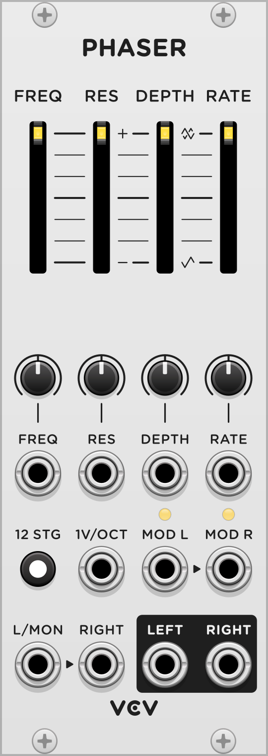
VCV Phaser
The sound of a phaser is similar to a chorus and flanger effect, except instead of processing signals through delay lines, each channel is sent through a chain of all-pass filters, shifting the phases of the signal’s frequencies. When combined with the dry signal, notches are created in the frequency spectrum, and if the cutoff frequency of the all-pass filters is modulated, this creates a familiar swirling phaser sound.
Signal path
VCV Phaser contains an all-pass chain for each L/MON and RIGHT input and can operate in mono, stereo, or mono-to-stereo modes. Each all-pass-filtered (wet) signal is mixed with the original (dry) signal and sent to the LEFT and RIGHT outputs.
Right-click the panel and select “Invert left wet signal” to invert the left channel’s all-pass-filtered signal before it is combined with the dry signal.

The FREQ fader adjusts the base cutoff frequency of the all-pass filters.
RES adds feedback to the all-pass filters by re-injecting the wet signal into the input of the filter chain. A negative resonance value injects an inverted wet signal, resulting in a different tone.
The cutoff frequency is modulated by an internal sine LFO. The DEPTH fader controls the amount of this modulation, and the RATE fader controls the frequency of the LFO. Negative depth values apply the same modulation amount to both channels. Positive values apply opposite modulation amounts to each channel, with 0° and 180° phase, creating a rotating stereo effect.

External modulator
An external CV signal can be added to the internal modulation for the left and right channels using the MOD L and MOD R inputs. This allows a complex waveform, sequence, or any arbitrary CV signal to control the all-pass cutoff frequencies. If MOD R is unpatched, the MOD L signal is used for both channels.
All-pass filter stages
The 12 STG button doubles the number of all-pass filters in each channel from 6 stages to 12 stages. This creates a more pronounced tone character.
At extreme resonance values, the phaser can nearly self-oscillate. This can add extra harmonics to the signal, or produce a plucked string-like sound when triggered by a short burst of sound.
The module can therefore behave like a complete synth voice when DEPTH is set to zero to avoid vibrato. The base note is set by the FREQ fader, defaulting to the note C5. The V/OCT input is calibrated to track pitch at 1V/octave, and the decay of the sound can be adjusted with the resonance fader.
Starter tip
Feedback inversion can be achieved by enabling “Invert left wet signal” and setting resonance to a large negative percentage. This creates a very different phaser tone with a vocal character.
Expert tip
VCV Phaser can be “pinged” using a short trigger or noise burst with an extreme negative resonance setting. With the 12 STG button enabled to add extra harmonics, this creates a rich metallic percussion sound.
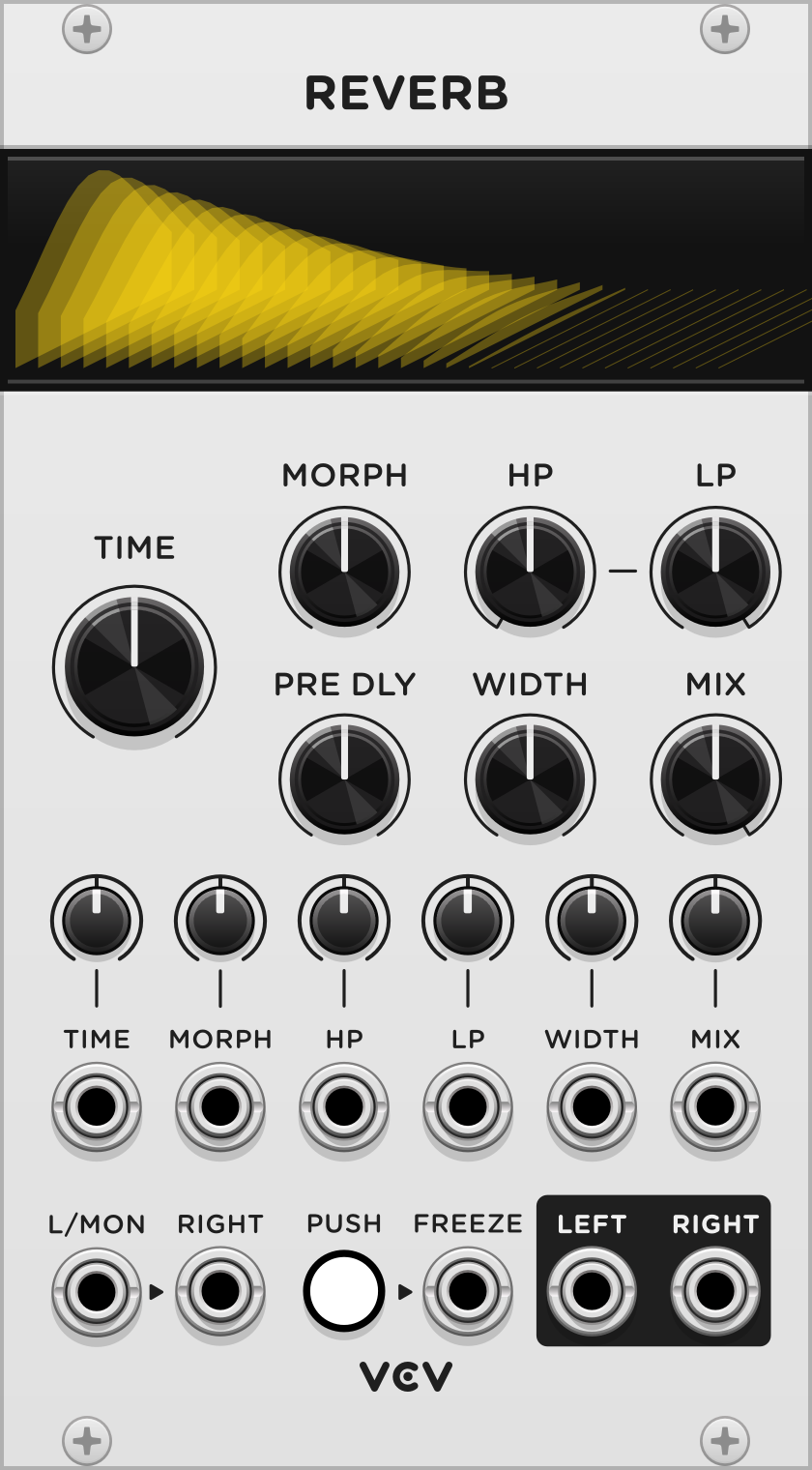
VCV Reverb
Reverb is the effect of sound reflecting off the walls and objects inside a space. VCV Reverb is an algorithmic reverb simulating reverb in a wide variety of natural rooms and surreal spaces, using a chain of delays, filters, and complex feedback loops.

Signal path
VCV Reverb processes L/MON and RIGHT audio inputs with a reverb algorithm and can operate in stereo or mono-to-stereo modes. Each processed (wet) channel is mixed with the unprocessed (wet) input according to the MIX parameter and CV input.

The TIME parameter sets the duration of the reverb tail in seconds, specifically the approximate time for the reverb signal to decay by -60 dB.
MORPH controls the characteristic of the reverb sound, by adjusting the mix of internal delay taps.
The HP and LP parameters set the cutoff frequencies of the high-pass and low-pass filters inside the reverb algorithm.
PRE DLY (pre-delay) specifies the amount of time to delay the dry signal before processing. In a physical room, this corresponds to the time between a sound and its shortest reflection in the space. For example, if the closest wall in a room is 3 m (10 ft), the first reflection will return back to the source in 18 ms, so this is a reasonable choice to simulate a room of this size.
The stereo image of the reverb can be reduced using the WIDTH parameter. At 0% width, the wet signal is mono, although it can be mixed with a (possibly) stereo dry signal.
The FREEZE button and gate input freezes the internal state of the reverb processor and blocks incoming audio, creating infinite reverberation.
Display
VCV Reverb displays a waterfall plot of the reverb’s impulse response. The left-to-right axis is time, front-to-back axis is frequency, and the height of each line is amplitude in dB.
Starter tips
The HP and LP filters play an important role in the sound of the reverb. High-pass filtering avoids muddy reflections, while low-pass filtering shortens the decay of shimmer.
This module can be inserted in serial to the end of a signal chain, using the MIX parameter to adjust the dry/wet balance. Alternatively, you can process audio in parallel by setting MIX to 100% and using a mixer module to combine the dry and wet signals. The send/return bus of a mixer module can be used to apply the same reverb to multiple tracks with different send levels.
Expert tips
VCV Reverb can act as an ambient drone voice by sending a short tone and holding FREEZE. The drone can be modulated using Reverb’s MORPH and filter parameters.
Gated reverb is a classic 80’s effect used on snare drums. It can be reproduced by using a noise gate module on a reverberated drum signal, with the dry signal as the sidechain. Alternatively, an envelope follower on the dry signal can modulate VCV Reverb’s TIME, so that higher envelope signals produce longer decay time.
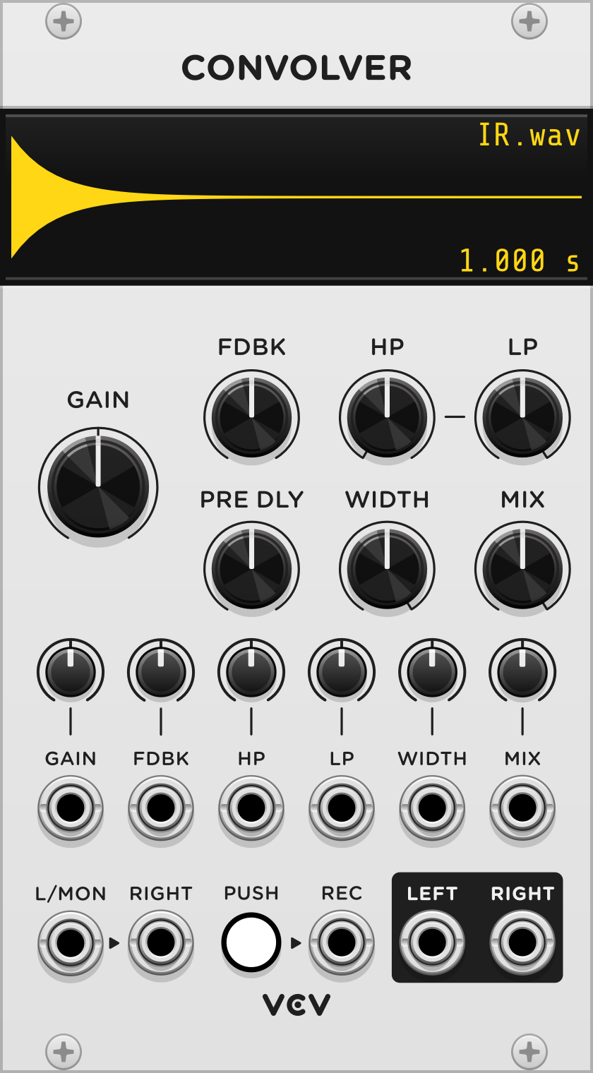
VCV Convolver
Convolution is an effect that mimics the sound of an acoustic space using nothing but a recording of an impulse (such as a balloon pop or hand clap) inside the space. This recording is called an impulse response (IR) and can be obtained by recording your own, downloading or purchasing online, or by using VCV Convolver’s selection of 26 included IRs.

VCV Convolver is a zero-latency convolution processor that can load mono/stereo IRs up to 60 seconds in WAV format.
To load an IR, click the IR display or right-click on the module’s panel and select “Load IR”. Once loaded, the IR waveform, filename, and duration is shown on the display.
The loaded IR can be stretched or reversed via menu options by right-clicking on the panel. Stretching changes the duration and pitch of the IR simultaneously.
Signal path
VCV Convolver processes L/MON and RIGHT audio inputs with a reverb algorithm and can operate in mono, stereo, or mono-to-stereo modes. Each processed (wet) channel is mixed with the unprocessed (wet) input according to the MIX parameter and CV input.

The GAIN parameter sets the input wet gain. Impulse responses are normalized by their root-mean-square when loading to equalize their volume level, but it is sometimes useful to further adjust the convolver’s volume.
A feedback loop allows the convolved audio to be mixed back into the input, to be pre-delayed and convolved yet again. FDBK adjusts the attenuation of the feedback loop. Warning: It is possible to create runaway feedback loops by increasing FDBK beyond a particular value for each IR. Fortunately, Convolver soft-clips audio output to prevent loud output signals, but it is a good idea to increase FDBK cautiously.
The HP and LP parameters set the cutoff frequencies of the high-pass and low-pass filters before the signal is convolved.
PRE DLY (pre-delay) specifies the amount of time to delay the dry signal before processing.
The stereo image can be reduced using the WIDTH parameter. At 0% width, the wet signal is mono, although it can be mixed with a (possibly) stereo dry signal.
Impulse response recording
VCV Convolver allows recording an impulse response in real-time. Patch a signal into L/MON and RIGHT inputs, and send a gate to the REC input or hold the adjacent push button. When recording stops, the recorded IR is immediately loaded and used for convolution processing.

Starter tips
Just like VCV Reverb, the MIX parameter can be set to 100% for parallel (send) processing, or a desired dry/wet balance for serial (insert) processing. 100% mix is recommended for guitar cabinet and microphone IRs.
When recording an impulse response on the fly, typically a gate is used in the patch to produce the impulse. This gate can be used to start recording at the exact sample the impulse begins, so the convolver can process with zero delay. The gate can be configured to stop when the impulse has sufficiently decayed, so convolved audio does not abruptly stop reverberating.
Expert tips
VCV Convolver can self-oscillate using the FDBK parameter to create drones or rhythmic pulse effects, similar to “no-input mixing” in noise music. Adjust PRE DLY to control the “tempo” of the feedback, and HP and LP to control the timbre.
Any type of sample can be loaded as an impulse response. Use a drum loop as an IR to process a melodic voice to create unusual rhythmic effects. Use a piano chord sample to process a percussive voice to create a tuned resonance sound. You can even convolve a sample with itself, and optionally stretch the IR to create a slower, lower pitched sound.
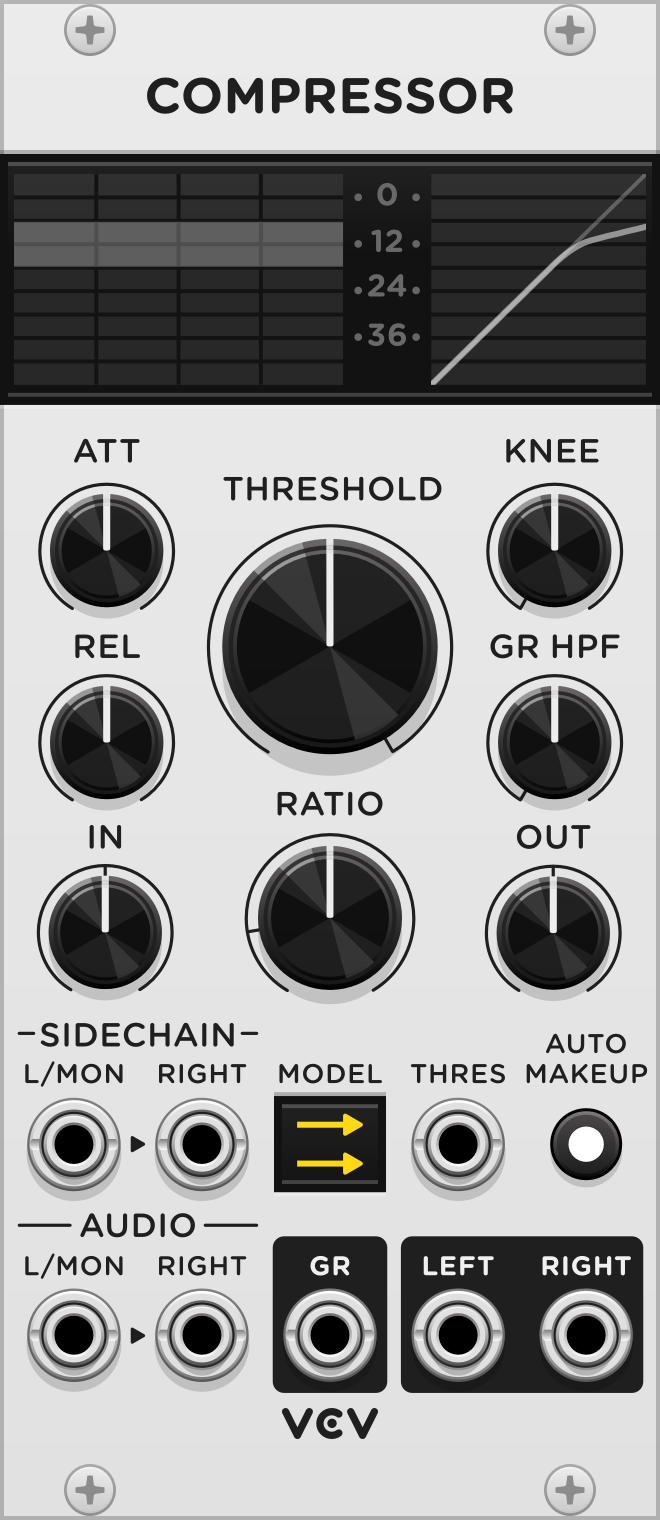
VCV Compressor
Dynamic range compression is a popular audio effect that makes loud sounds quieter or quiet sounds louder. This decreases (or compresses) the audio’s dynamic range, which is the difference in volume between the quietest and loudest sounds. Skillful application of compression is vital for making audio tracks sound balanced in a mix, professionally polished, and consistent over time.
VCV Compressor can process mono and stereo audio with an optional mono or stereo sidechain signal. It works by measuring the volume level over time of the AUDIO input signal (or the SIDECHAIN audio input instead if patched) using an envelope follower with a rise and fall time set by the ATT and REL knobs.
The envelope signal is sent to a gain reduction circuit which applies attenuation to the audio signal based on the volume envelope. Additional output gain can be applied if needed, and the audio is sent to the outputs.

When a sidechain signal is patched, the envelope follower “listens” to the sidechain signal instead of the audio input, yet gain reduction is applied to the audio input.

THRESHOLD is the minimum audio level in dB where gain reduction begins to occur. Audio signals below the threshold level are unaffected, meaning that no attenuation is applied. Threshold can be modulated with CV, with 10V applying no modulation and lesser voltages applying linear attenuation to the threshold level.
RATIO is the strength of the gain reduction applied for audio beyond the threshold level. A higher ratio results in more aggressive compression above the threshold. For example in an ideal compressor, a ratio of 4/1 means that an increase of 4 dB beyond the threshold gives only 1 dB of volume increase in the audio output.

VCV Compressor can also act as an expander, performing the opposite of compression. When the ratio is less than 1/1, loud input audio results in louder output audio. This effect is called expansion, and it increases the dynamic range of an audio signal. For example, a ratio of 1/2 means that an increase of 1 dB results in an increase of 2 dB in the audio output.

KNEE adjust the sharpness of the transition between uncompressed and compressed signals around the threshold. A hard knee of 0 provides no transition from 1/1 to X/1 ratio as the threshold is passed. A soft knee above 0 provides a smooth transition between 1/1 and X/1 ratio over a specific number of decibels.
The GR HPF knob applies highpass filtering from 10–1000 Hz in the envelope detector circuit to avoid reacting to sub-sonic or bass energy, which can cause unwanted pumping behavior in the output. Highpass filtering is not applied to the audio signal itself, only the gain reduction signal chain.
The GR output produces a voltage based on the gain reduction applied to the audio level. The scale is linear, with 10 V meaning no attenuation and 0 V meaning full attenuation (mute), so the CV signal can be used to mimic gain reduction using an external linear VCA module. If you prefer logarithmic scale, with 0 V meaning no gain reduction, 1 V meaning -6 dB, 2 V meaning -12 dB, etc., then right-click the module’s panel and set “GR output” to “Log”.
The AUTO MAKEUP switch automatically compensates for the gain reduction by adjusting the output level based on the threshold level to maintain consistent loudness while adjusting the threshold.
Models
VCV Compressor includes 6 models based on modern digital and vintage analog hardware compressors. Each model applies its own distinct character to the envelope follower, gain reduction, and audio amplifier sections of the signal chain. Click the MODEL button to cycle through the 6 models, or right-click to directly select a model.
 Feed-forward: Idealized model using an input peak detector to control gain reduction.
 Feedback: Idealized model that monitors the output peak to control gain reduction. Uses an iterative zero-delay solver for stability.
 VCA: Based on the 4000 Stereo Bus Compressor, using VCA chips for its audio and gain reduction signal chains. This model is said to be transparent and punchy.
 Optical: Emulates an opto-coupler, a lamp enclosed with a photoresistor in an opaque box, for level detection which reacts more slowly for loud signals and more quickly for quieter signals. This model uses a feedback circuit similar to the 1960’s LA-2A compressor. Unlike the LA-2A, VCV Compressor allows you to adjust the attack, release, ratio, and knee parameters.
 FET: Based on the 1960’s 1176 compressor using a solid-state field-effect transistor amplifier.
 Tube: Based on the 1950’s RCA BA28A compressor. Uses an amplifier engine that adds harmonic character of tube amplifiers.
All models are oversampled 2x by default but can be adjusted from 1–16x to balance performance and stability by right-clicking the panel and setting “Oversample”.
Meters
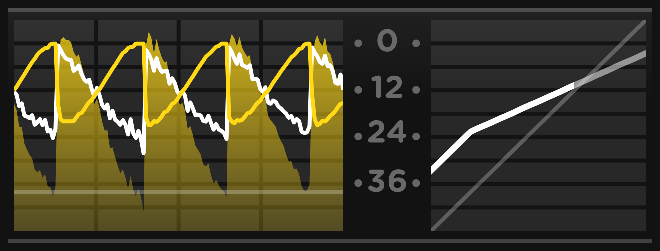
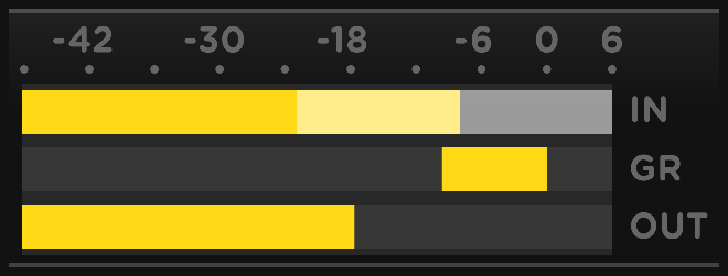
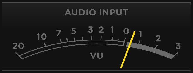
VCV Compressor includes 3 meter modes to visualize the input, sidechain, gain reduction, and output levels. Click the display to cycle through all modes, or right-click to directly select a mode.
- Scope: Shows the last 2 seconds of audio levels between -48 dB and +6 dB. Input level is shown as a dark color, output level is a light color, and gain reduction is a bright line. An input/output plot is on the right, showing the threshold and ratio with an optional knee.
- Linear: Shows immediate audio levels on a linear decibel scale between -48 dB and +6 dB. The threshold is a white overlay over the audio input level (or sidechain level if patched).
- VU: Physically-modeled classic VU meter displaying input, sidechain, gain reduction, and output levels between -20 dB and +3 dB. Perfect for those comfortable with analog studio hardware.
Starter tips
New York compression / parallel compression: Process drums with VCV Compressor using a high ratio and threshold, then mix the result with the dry signal using VCV Fade. This gives you the best of both worlds of the signal’s original dynamics and a crushed, punchy version.
Expert tips
Typically studio compressors can only compress the volume level of a signal, but in VCV Compressor the GR output can control anything—a filter’s cutoff frequency, an LFO’s speed, a reverb’s wet/dry mix, etc.
VCV Pro Changelog
2.2.0 (2024-07-18)
- Add Compressor.
2.1.1 (2023-08-13)
- Use dark-themed ports.
2.1.1 (2023-08-13)
- Add dark panels.
2.1.0 (2022-12-31)
- Add Reverb and Convolver.
2.0.2 (2022-10-20)
- Chorus, Flanger, Phaser
- Apply monophonic CV input signals to all polyphonic voices, to comply with the VCV polyphony standard.
2.0.0 (2022-10-10)
- Add Chorus, Flanger, and Phaser.